Or Gate Circuit Diagram Using Transistor
Gate circuit transistor logic inverter using Nor gate: what is it? (working principle & circuit diagram) Cmos xor gate circuit
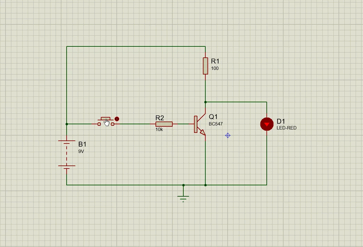
transistors - Can anybody explain how the inverter circuit works
Gate transistor using circuit diagram transistors based engineersgarage fig Gate transistors using logic gates transistor resistor circuit diodes diagram make discrete purpose values different why schematic board electronics emitter Circuit transistor simple gate switch led acts strangely unconnected voltage make electrical electronics stack
Xor gate using transistor circuit diagram
Implementation of a not gate with two transistorsCircuit inverter transistor led switch gate logic gates transistors gif battery explain anybody works off petervis shouldn loop affect forms Gate transistor circuit transistors resistorGate transistor using circuit diagram improved schematic designing version circuits.
Nand gate implementation transistors circuit diagram electricalNand gate circuit diagram 2 input diode transistor logic And gate using transistorGate transistor logic gates input output circuits digital circuit transistors truth nand led build different made questions current electronics source.

Gate transistor transistors circuitdigest vivekanand circuits
Circuit diagram of nand logic gateGate transistor using circuit diagram schematic simple designing resistor simplest sharing two circuits emitter paralleled followers common And gate transistor diagramXor transistor.
Not gate circuit diagram using transistorNor transistor transistors electrical4u parallel bipolar Six-transistor xor gate.Xor gate diagram.

Gate transistor circuit logic terminals reminder input two
From transistors to micro-processorsGate transistors two implementation transistor why electronics lower question need stack just Or gate: what is it? (working principle & circuit diagram)Not gate circuit diagram on breadboard.
Transistor gate using diagram circuit based showing working engineersgarage led figAnd gate transistor diagram Digital electronics-logic gates basics,tutorial,circuit symbols,truthWhat is not gate inverter, not logic gate inverter circuit using transistor.

And gate diagram transistor
Nand logic gates transistor diode nor transistors diodes 5v rtlDesigning or gate circuit using transistor Gate circuit diagram transistor using electrical4u principle working inputs shown such below twoDesigning an and gate using transistors.
Working of or gate using transistorElectronic – and gate output when inputs are open – valuable tech notes Simple nor gate transistor level diagram circuit schematic logic input electrical digital question stackAnd gate using transistor.

Why are or gates using transistors different from or gates using diodes
Is this npn transistor and logic gate practical?Digital logic Transistors nand gate transistor circuit circuits processors micro integrated 101computingDesigning or gate circuit using transistor.
Designing or gate circuit using transistorGate transistor logic npn schematic using circuit practical questions circuitlab created stack Transistor xor gate[diagram] block diagram xor.

Transistor and gate
Working of not gate using transistorXor gate transistor electroniques zpag english .
.

and gate transistor diagram - IOT Wiring Diagram

Is this NPN transistor AND logic gate practical? - Electrical

AND Gate using Transistor | EngineersGarage

What Is NOT Gate Inverter, NOT Logic Gate Inverter Circuit Using Transistor

From transistors to micro-processors - 101 Computing

Implementation of a NOT gate with two transistors - Why not one